
")

DESCRIPTION:
Flow regulators are used wherever it is required to limit and control the flow in order to protect objects and devices below the place of installation of the regulator against excessive amount of water.
MATERIALS:
VRP-K regulators are made of stainless steel (e.g. AISI 304/304L – 1.4301/1.4307), acid-resistant steel (e.g. AISI 316/316L – 1.4401/1.4404) or any other, depending on customer requirements and conditions at the installation site.
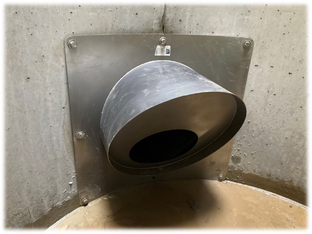
MOUNTING:
The VRP-K regulator is mounted by screwing it to the chamber wall using anchors. The seal between the wall and the regulator is provided by a porous EPDM gasket or one of the commonly available sealing compounds. Other mounting methods are possible, such as clamping on the pipe, sliding into the socket or spigot end of the pipe, etc.
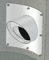
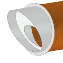
Mounting options:
 |
 |
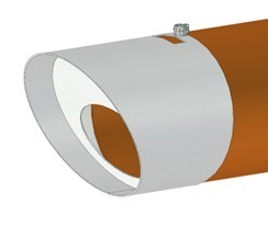 |
| a) Screwed to the wall | b) Inserted into the pipe | c) Clamped to the spigot end of the pipe |
ADDITIONAL OPTIONS:
A number of additional options are available, such as a grid at the regulator's inlet, additional fastening elements, an emergency shut-off, or an adjustable plate that changes the regulator's characteristics.
DOCUMENTATION:
Standard documentation supplied with the delivery includes: the national declaration of performance, technical and operational documentation along with the operating and assembly instructions. On request, we provide dimensional drawings, characteristic curves, material certificates, etc.
REGULATOR SIZING:
Each regulator is sized individually for a specific application.
Flow Chart of Orifice Flow Regulator VRP-K
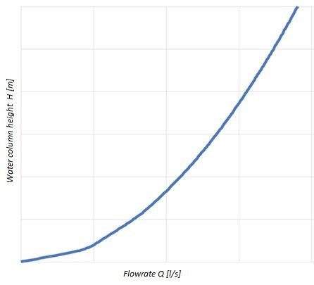
The following data is needed to select the regulator: Required maximum flow [l/s] for a given water column in front of the regulator [m], diameter of the outlet pipe in which the regulator is installed [mm] and information on the location of the regulator's installation: round chamber - specify the diameter, or a flat wall.
| Data sheet: |
|
